CLUB 500
RACE BOX
By Reg. Crompton
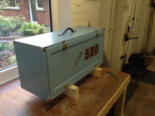
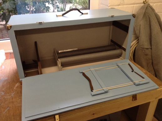
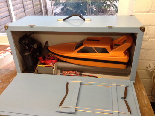
Here are the instructions on how to make a handy box to take to your club 500 race meetings, you will have all you bits and pieces all in one place along with a folding boat stand on which to service your boat.
Below is the cutting list which you can cut yourself or do as I did which was to take to a local wood yard and get it all cut, the advantage I found was that all the cuts are square and accurate, which all adds to the speed of build.
The main body of the box is ¼” plywood.
¼ plywood
2 off 12”x 26” to form back and front of box
2 off 10”x 26”to form top and bottom of box
2 off 12½” x 10”to form the ends of the box
4 off 3½”x 8” to form the boat stands
2 off 9 ½” x 6”to form the wall and the handle backing
1”x ¼” strip wood
4 off 27” long
2 0ff 10” long
½” doweling
2 off 18” long
½” square wood
26 foot.
Hard ware
6 off 1½” Butterfly hinges
2 Toggle catches
1 handle ( flight bag/suitcase)
40 off ¾” wood screws, counter sunk
30 off ½” wood screws, counter sunk
6 off 3mm set screws ¾” long with nuts washers
Club 500 box
Assembly steps
1. Front and back panels. Glue ½”sq around the outer edges of both panels flush with the outer edges.
2. Top and bottom panels. Glue the front and back panels to the top and bottom panels to form an open ended box.
3. Edging. Complete the ½”sq edging, and glue in the top and bottom sections in the open ends of the box.
4. End panels. Glue the end panels onto the ends of the open ended box.
At this point you have a totally enclosed box, this is a good time to add a few wood screws ½”x 2s, or similar at equidistant points around the box to add strength, 4 around the ends and 6 around the long panels.
5. Cutting out the door. Choose the front of the box and mark a line 1” from the outer edge all around the perimeter of the front panel, cut around this line with a jig saw taking care in the corners as this cut out will form the door.
6. The door. Using 1”x ¼” wood strip, glue a piece along the bottom, flush with the bottom edge of the door, this strip should be ½” longer on each end of the door panel. Glue wood strip around the remaining 3 sides of the door ½”on the door and ½” off forming a rebate on the 3 sides, butt joins are OK.
7. Mounting the door. Lie the box on its back and place the door in position, if its tight adjust the outer frame with a craft knife.
Glue a length of 1”x ¼” wood strip along the full length of the bottom edge of the box frame, this strip will form a foundation for the door hinges,
Fix the hinges to the bottom of the door and to the bottom strip of wood.
Fix the 2 toggle catches to the top edge of the door . NB the caches may need some adjustment of slight modification to suit your requirements’.
8. Inner boat rake. Take two of the 8”x 3½” pieces and mark the long sides top and bottom, mark 3 vertical lines, one in the centre and two
1 ¾” from each end of the piece.
Draw 2 horizontal lines, 1, 1” from the bottom and 1 2” from the top,
On the top edge mark a line from the top corners to the centre of the 1” line to form a vee, cut this vee out.
At the intersection of 2” and the 1 ¾” lines drill two holes to suit your doweling, now cut ½” off the bottom of one of the pieces and glue this piece to the inside of the right hand side panel of the box.
The remaining piece needs a ½” sq piece of wood glued to its bottom edge for reinforcement.
Assembly. Drill two screw hole in right hand end panel in the centre of the drilled dowel holes, fit the dowels in place and fix with glue and two screws from the outside.
Slid the other piece of ply onto the other end of the dowels and glue in a position with about a ¼” protrusion, glue the piece to the base and fix with screws from the underside utilising the ½” reinforcement.
The dowels used on this rack can have pipe insulation added to cushion the boat in transit.
9. Pit boat rack. Take the two remaining 8”x 3 ½” piece of ply and mark top and bottom on the 8” sides, mark two horizontal lines, 1 off ½” from the top edge and 1 off 1” from the top edge.
Mark 3 vertical lines one in the centre and two ½” in from each edge
Now cut down the two outer lines for ½” , then cut from the bottom of these cuts to the centre point on the lower line which is 1” from the top to form a vee inside two ½“x ½”up stands.
Reinforce the bottom edge of these pieces with 1”x ½” strip wood.
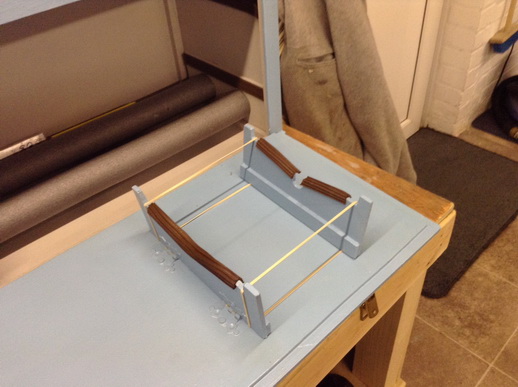
10. Mounting pit rack. Position one piece of the rack 4” in from the right hand edge of the inside of the opened door in a central position with the reinforcement to the inside and the hinges to the outside and the second piece, 6” on toward the centre with the reinforcement inward toward the first piece and the hinges to the outside, this done both pieces of the rack should fold outward from each other and lie flat when not in use.
Place two rubber bands around the outer edges of the rack with more tension on the lower edge, this will help keep the stand in the folded position when not in use and the remaining tension will hold the stand upright when being used for boat maintenance.
The hinges are screwed to the boat stand sections but due to the lack of thickness in the door the other half of the hinges should be bolted to the lid and the bolts cut and filed flush.
11. Wall section. The wall is made up from one of the remaining pieces of 9 ½”x 6” plywood. Position the wall to the left hand side of the box with enough room to store your radio in an upright position plus a little padding for protection, you will need to cut out two notches to fit over ½” wood box framing and cut the wall across it outer corner to aid radio removal, glue a piece of ½”sq along the bottom edge of the wall and glue and screw to box base.
12. Handel fitment. Glue the remaining piece of ply 9½”x 6” to the underside of the box top in a central position and bolt the handle through the top and the extra ply reinforcement
13. To get the best finish to your new box it is advisable to remove all the fittings prior to painting and reassemble when the finish is to your required standard. It is also worth over counter sinking all the screw holes to allow room for some filler it enhance the finish.
Images below.

A simple but effective way to run two shafts from one motor, With the help of gears and pulleys
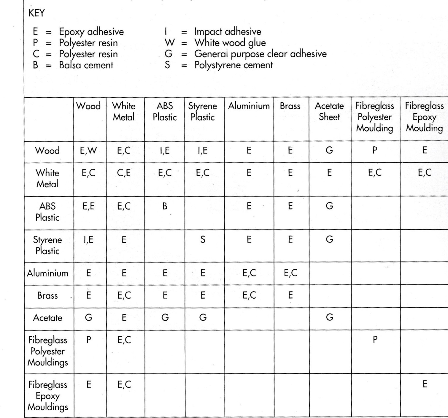
The chart above will give you some idear, off fixing different materials together.
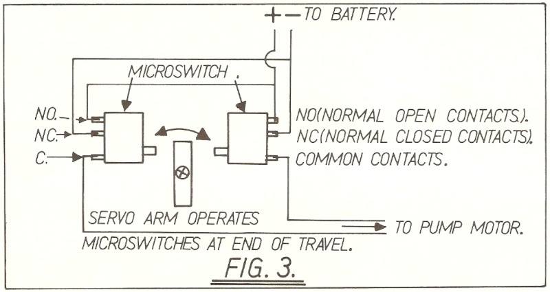
The above photo, came from a friend, He's version of a Bow Thruster, useing one servo, two micro switches, and a standard water pump 12 volt, The wiring diagram noted as fig 3 is how he done it, he said it save's a lot of money and space, in the bottom of the hull, and the bonus is very small hole's in the hull.